
All, Whole Body Health
Using Digital Technology for Complex Aesthetic Challenges
Feb
Introduction
Traditional analog diagnostic methods used to treat complex aesthetic challenges can be effective but often are inefficient, inaccurate, and do not precisely reflect definitive surgical or restorative solutions. Digital diagnostic techniques allow dentists to easily and economically fabricate surgical guides from CBCT while virtually placing implants precisely by standardizing an implant’s size and the angle and depth of placement. This approach removes many of our implant complications. Unfortunately, despite their importance, scanning and virtual planning are not utilized enough, making patient communication and treatment more difficult. This case demonstrates a unique and innovative digitally generated systematic approach to guide the practitioner through a process that can expedite important decisions, provide unique patient communication options, and improve the predictability of aesthetic outcomes.
CASE REPORT
Diagnosis and Treatment Planning
A 60-year-old male presented with an unsightly, monochromatic bridge; a crooked smile; and a lack of buccal posterior fullness (Figure 1). He reported that one abutment tooth had a history of repeated fracture. His initial goal was to obtain a “natural appearance.” He wondered if implants were an option for him and wanted to help design the shape and form of the new front teeth. He was unhappy with the appearance of his current anterior bridge, reporting that the teeth looked like piano keys and the incisal edges were not aesthetic.
A comprehensive dental exam, including medical and dental histories, full-mouth radiographs, a TMJ exam, periodontal charting, bite registration, functional analysis, and clinical photos, was accomplished. Radiographic evaluation showed a long span bridge from teeth Nos. 6 to 11. The abutment teeth were structurally compromised due to past endodontics and post and core buildups.
The photographic evaluation involved a detailed analysis of midlines, the tissue display, lip asymmetry, length, and shape. In a Duchenne smile, neither the patient’s maxillary gingival zeniths nor interproximal papillae were visible. The smile was asymmetric, with his upper right lip raising more than the left side. The lower lip had a medium display, with all lower tooth structure except the gingival zenith showing in the Duchenne smile. There was a midline discrepancy between the upper and lower midlines.
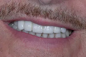
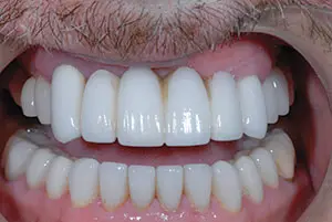
Figure 1. Note the monochromatic bridge, crooked smile, and lack of fullness in the buccal corridor.
Figure 2. Lip retraction revealed the proclined anterior teeth, as well as their “piano key” appearance.
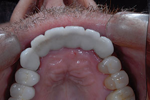
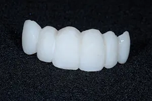
Figure 3. The hollowed-out lingual morphology made it difficult for the patient to speak a crisp “S” sound.
Figure 4. The shapes of the teeth followed the golden rule of proportion. The incisal embrasures on the right were more open, allowing the patient to choose the tooth form that was most pleasing to him.
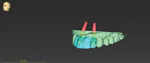
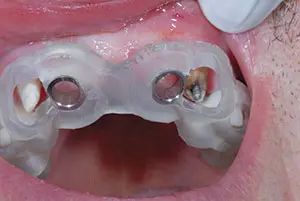
Figure 5. The apex of the No. 10 implant was tipped mesially to respect the 2-mm space needed to protect the angled root of the cuspid.
Figure 6. The surgical guide fit was verified.
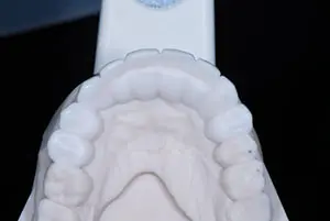
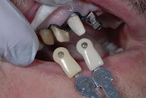
Figure 7. Note the deliberately over-contoured palatal design on the diagnostic wax-up to allow the chairside adjustment of speech.
Figure 8. Two different shade tabs were used to communicate the different stump shades.
The 6 anterior porcelain restorations appeared too dominant and were in proclined positions. The width of the 6 anterior teeth were identical and resembled piano keys (Figure 2). Although he had a low smile line, he would manually lift his lip to evaluate the tooth shapes and forms in a magnification mirror, and he did not like what he saw. A porcelain-fused-to-metal bridge was present on teeth Nos. 13 to 15, and it was more than 30 years old. The upper left was asymptomatic, and he was satisfied with the bite, function, and cleanability of that bridge.
His speech was slushy when pronouncing the “S” sound. Evaluation of the anterior bridge palatal anatomy revealed a hollowed-out design that anatomically created the inability to close this speaking distance (Figure 3).
A surgical consult was recommended to evaluate the edentulous sites of teeth Nos. 7, 10, and 14 for implant placement to reconstruct his dentition. At the follow-up consult, he elected to place only the 2 anterior implants. He did not desire to build out the left side of his smile corridor by replacing the upper left bridge because this area was invisible due to the lip laxity on his left side. He was motivated to have the anterior 6-unit bridge removed as soon as possible. He agreed to proceed with a 9-unit restorative treatment plan, including an implant-supported bridge from teeth Nos. 7 to 10 and single porcelain crowns on teeth Nos. 4 to 6, 11, and 12.
Preoperative records can be taken in either digital or analog format or both, creating a hybrid workflow, depending on the needs of the case. An intraoral scan (iTero Element 5D [Align Technology]) and the CBCT scan were sent to the lab for implant placement design of teeth Nos. 7 and 10 and the fabrication of a surgical guide. A PMMA provisional could also be milled from intraoral scans. Since this patient desired immediate changes in the shape and form of the restorations, a chairside analog impression was taken (Template Clear [Clinician’s Choice Dental Products]) in an anterior dual-arch impression tray (Quad-Tray XL [Clinician’s Choice Dental Products]) over the existing maxillary porcelain teeth. The patient was anesthetized, and the anterior bridge was removed. A long-span, semi-permanent, self-curing composite provisional bridge (LuxaCrown B1 [DMG America]) was fabricated. Luxacrown was selected because of its flexural strength and the clinician’s ability to directly modify the provisional shape and form after a 5-minute set with flowable composite (Beautifil Flow Plus X FOO B1 [Shofu Dental]).
The provisional bridge was purposely fabricated with incisal embrasures and tooth forms that were different on the right and left sides. The patient could then evaluate each form and decide which he preferred (Figure 4).
Virtual Planning for Implant Placement
An implant should be placed at least 2 mm from the adjacent tooth.2 Since tooth No. 11 had an angled root, the apex of the implant replacing tooth No. 10 needed to be tipped mesially (Figure 5). It was possible for the implant replacing tooth No. 7 to be placed parallel to tooth No. 6 as it was in proper alignment. This created a potential divergent path of insertion for the final prosthesis. The surgeon approved the plan, and the surgical stent was fabricated.
Surgery Day
On surgery day, the patient was appointed first with the restorative dentist. The provisional bridge was evaluated, and preferences for the final prosthesis were discussed. The patient preferred the longer right lateral shape and desired to have smaller incisal embrasures. Flowable composite was added to tooth No. 7 to lengthen the tooth and make it look the more square. Composite was also placed on the buccal and incisal of the bicuspid porcelain as a direct mock-up to gain the desired buccal corridor fullness for teeth Nos. 4, 5, and 12 as well as to guide the shape and form of the newly prescribed 9-unit diagnostic wax-up.
An intraoral digital scan, a backup analogue PVS full-arch impression, and bite registrations (Virtual CADbite [Ivoclar Vivadent]) were taken.
After anesthetic administration, the provisional bridge was removed, and the surgical guide try-in verified the fit. The provisional bridge was then placed over the abutments with no cement, and the patient drove to the surgeon’s office. The surgeon removed the provisional bridge and used the guide to place bone level tapered 4.1 RC × 12 Straumann implants in the lateral incisor sites of teeth Nos. 7 and 10 (Figure 6). The provisional bridge was then recemented (TempoCem ID [DMG America]).
Osseointegration Period
During the 3 months of implant osseointegration, the porcelain restorations were removed from both upper bicuspids, and the preparations were refined. A new 9-unit provisional was created in a lighter shade (Telio CS C&B BL3 [Ivoclar Vivadent]), extending from teeth Nos. 4 to 12. This healing period also provided an opportunity to address the slushy speech resulting from the prior bridge’s palatal contour (Figure 7).
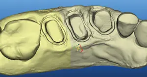
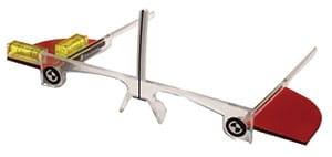
Figure 9. A stone model view of a scan of teeth Nos. 4 to 6.
Figure 10. Kois Facial Reference Glasses simplified capturing the correct head position in photos and allowed for precise measurements of any anatomic feature visible in the photographs
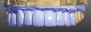
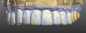
Figure 11. The ceramist first designed the teeth in 3Shape software to match the scanned provisionals (shown in purple).
Figure 12. Intentional design changes can be seen in white.
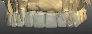
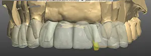
Figure 13. The design was laid over the preparations.
Figure 14. The design was superimposed over the implant abutments.
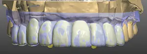
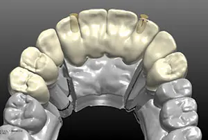
Figure 15. The exact duplication of the approved provisional was verified in the prosthesis design.
Figure 16. The angled screw technology allowed the screw access to be moved away from the incisal edge.
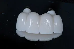
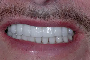
Figure 17. The final bridge duplicated the patient-approved contours from the provisional exactly.
Figure 18. The final result was a pleasing smile that captured the patient’s preferred contours and tooth lengths and an increased buccal fullness. Note the improved smile symmetry, revealing more tooth structure on his left than with the previous bridge.
Approximately 1 mm overbite and 1 mm overjet between the upper and lower central incisors must be present so the tongue can close this distance to produce a crisp “S” sound.3 Correcting the slushy speech would also require altering the palatal contours in the final restoration. The lab constructed the new provisional following a diagnostic wax-up that added bulk to the lingual palatal form of the anterior teeth so that the mandibular anterior teeth would contact the palatal surfaces in MIP. This approach allowed the closest speaking space to be determined at the chair before the final prosthesis was made.
When the new provisional was tried in, MIP was recorded, then slight amounts of composite were removed from the palatal aspect of the anterior teeth. A delicate balance was necessary to ensure that there was contact with the lower teeth in MIP while retaining adequate bulk for proper speech. The functional occlusion was evaluated with the patient sitting up in the chair and chewing on thick 200-µm Articulating Paper (Bausch).
The patient returned 3 months post-surgery and gave written approval of the shape, form, and color of the provisional and requested that the new restorations be slightly lighter and brighter than his existing lower teeth.
An intraoral digital scan (iTero Element 5D) was taken of the approved provisionals to guide the ceramist in digital design. Shade tab photos were taken in the same plane as the provisional restorations to document the color, along with full-face photos.
The healing abutment was removed, the reverse torque test at 20 Ncm verified integration, and the impression coping was screwed into place. Complete seating of the abutments was confirmed with radiographs. A fixture level, full-arch impression (Honigum [DMG America]); opposing impressions (AccuDentXD [Ivoclar Vivadent]); and bite registrations (Virtual CADbite ) were recorded. The stump shade photos were taken (Figure 8). On the right side, 2 different shade tabs were used to communicate the different stump shades. This information is important for the ceramist, particularly when they are working with a translucent zirconia.
Figure 9 is an example of a stone model view of a scan of teeth Nos. 4 to 6.
An analogue impression technique was also used, the model was scanned, and the scan was imported into the 3Shape design software.
Digital Design for Fabrication of the Translucent Zirconia Restorations
Photo orientation and head position are critical to aesthetic digital design. The retracted full-face photo was taken with the patient wearing Kois Facial Reference Glasses4 (Figure 10). The glasses are designed to simplify capturing the correct head position in photos. In addition, the distance between the targets on the glasses (140 mm) transforms the information in a photograph to allow for precise measurements of any anatomic feature visible in the photograph.
The approved provisional prototypes were scanned into the 3Shape software. The teeth are designed in the software first by matching the provisionals (purple) (Figure 11) to the patient-approved shapes. Intentional design changes dictated by the laboratory prescription show up as white (Figure 12). The design is then laid over the preparations, and the proper thickness of material is verified (Figure 13).
The proposed zirconia design was superimposed over the implant abutments (Figure 14).
Exact duplication was then verified by superimposing the approved provisionals over the proposed design (Figure 15). A screw-retained design was selected to increase the ease of removal and also to decrease the risk of postoperative cement retention.
Upon evaluation of the design, it was noted that the implant angle was skewed, forcing the screw channel opening to be directed through the facial incisal edge. Straumann has created an angled screw technology to assist in changing the angle of the screw access by using TruAbutment angled screws and drivers (Figure 16).
An aesthetic zirconia material (IPS e.max ZirCAD Prime, shade BL1 [Ivoclar Vivadent]) was selected due to its aesthetic properties and high flexural strength. IPS e.max ZirCAD Prime is produced using Gradient Technology (GT), a unique manufacturing process that uses special powder conditioning to combine 3Y-TZP and 5Y-TZP oxide ceramic powders for high strength and aesthetics. Unlike multilayered materials on the market, which can have visible layers of color, the GT in IPS e.max ZirCAD Prime offers a seamless progression of shade and translucency.5 This provides a lifelike final restoration that shows no demarcation between stacked layers and offers a true material progression from dentin to enamel. In addition, this technology also allows this material to achieve high mechanical strength with a flexural strength of 1,200 MPa and a fracture toughness of more than 5 in its core region.
The design was positioned in the BL1 puck and milled. The units were removed from the puck, contoured, stained, and glazed. The titanium abutment was anodized and cemented inside the zirconia bridge (Ivoclar Monobond plus and Multilink Hybrid abutment cement).
The final result exactly duplicated the patient-approved contours from the provisionals (Figure 17).
Try-In
Anesthesia was administered, the provisionals were removed, and the tooth stumps were cleaned with pumice in a prophy cup. The IPS e.max ZirCAD Prime single units were tried in and evaluated for marginal fit and aesthetics. New titanium angled abutment screws were placed in the implants and were first hand tightened, then torqued using a TruAbutment driver to 35 Ncm in a wet environment. Aesthetic evaluation was done, and patient approval was given. Radiographic confirmation verified complete seating of the bridge.
Cementation
The restorations were sandblasted by the lab using alumina beads (50 µm) at 1 bar of pressure. The purpose of sandblasting is to increase surface roughness for improved mechanical retention. During the patient’s visit, the restorations were tried in. The phosphates in the saliva bond to the internal surface of the zirconia and must be removed to achieve high bond strengths. The zirconia restorations were cleaned by applying Ivoclean (Ivoclar Vivadent) to the intaglio surface with a reaction time of 20 seconds, followed by rinsing with water and air drying.
The zirconia restorations were cemented using a dual-cure, self- adhesive resin cement (SpeedCEM Plus [Ivoclar Vivadent]). SpeedCEM Plus contains MDP; therefore, the use of zirconia primer as a separate step was not required. The cement was extruded into the restoration, then seated. Excess cement was removed by tack curing for 1 second, then applying a liquid strip to avoid the formation of an oxygen inhibition layer. A final cure of 10 seconds per surface completed the cementation.
The bridge was torqued again to 35 Ncm to minimize the risk of screw loosening. The access opening was obturated with Teflon plumber’s tape, followed by composite. The implant models were archived in the patient’s records box. The recare protocol includes bone and soft-tissue monitoring every 6 months. The final result was a pleasing smile that captured the patient’s preferred contours and tooth lengths and an increased buccal fullness. His smile symmetry was improved, revealing more tooth structure on his left than with the previous bridge (Figure 18).
Read the full article by CLICKING HERE

Comments are closed.